Contents
Progress
This post follows on at quite a distance from my last post on the subject, and until recently I had not realised quite how long this project has been languishing on the bench. Like many of the electronics projects I undertake they need to be able to withstand being outside and exposed to weather conditions, dealing with packaging them to handle harsher environments is always the most difficult part.
For the same reason as above, I have also changed one of the key measurement components, the humidity sensor.
I am also dropping the Arduino Uno in favour of the Arduino Yún. I wrote a brief article on the Yún some time ago.
Packaging for the Outdoors
Progress is now being made, finally, on the assembly of the containing hardware of the device. The constituent parts of the detector, namely the box housing for the electronics including the IR detector and the thermostatically controlled heated aluminium mirror have been completed. Now I am in the process of mounting the parts together into a detector assembly. In addition I have made progress on a weather resistant external housing for the entire system to safely be exposed to the elements outside.
Detector Assembly
After thinking about things for a little while, I decided to mount the whole assembly on an acrylic base that will slide in and out of the back of the housing to make maintenance easier. This also keeps the IR detector and mirror at a calibrated distance and angle that should not change between hardware maintenance schedules.
The following photo shows the whole setup:
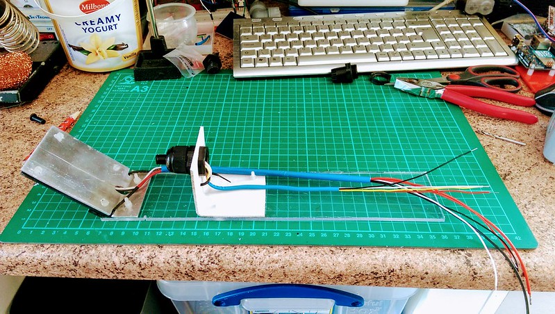
Detector and mirror assembly
The photo below shows the use of a external cable exit gland to hold the IR detector in place. The gland tightens around the plastic housing of the IR detector leaving enough flexibility for fine adjustment if required. The cables have been tidied up using some old heatshrink I had lying around from another project.
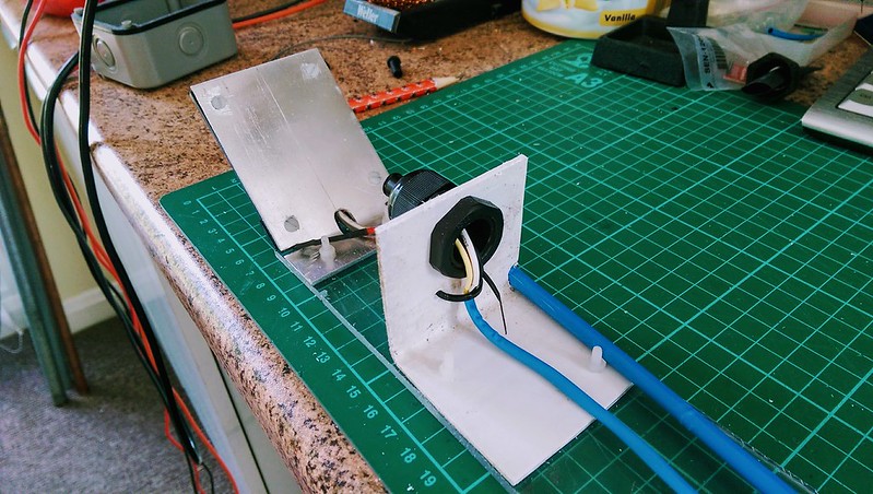
Another view of the detector and mirror assembly
Below you can see the wires exiting from underneath the aluminium mirror. The wires leading from the centre hole at the base go to a DS18B20, a temperature detector, there to measure the surface temperature of the mirror. The black and red wires on the outside edges are connected to heater wires underneath the mirror.
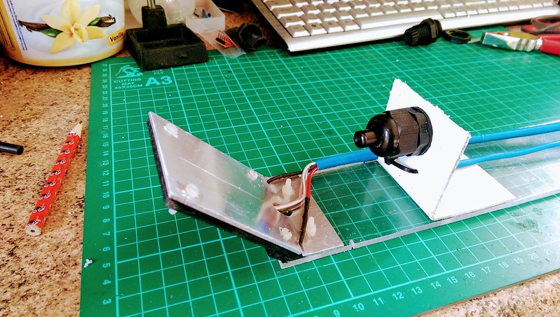
Another view of the detector and mirror assembly
Exterior Housing
Progress is also being made with the exterior housing for the whole setup. The exterior housing (white part) is made from spare 114 mm square section acrylic gutter downpipe. The box (grey) for containing the Arduino and power supplies is an external IP65 rated electrical junction box.
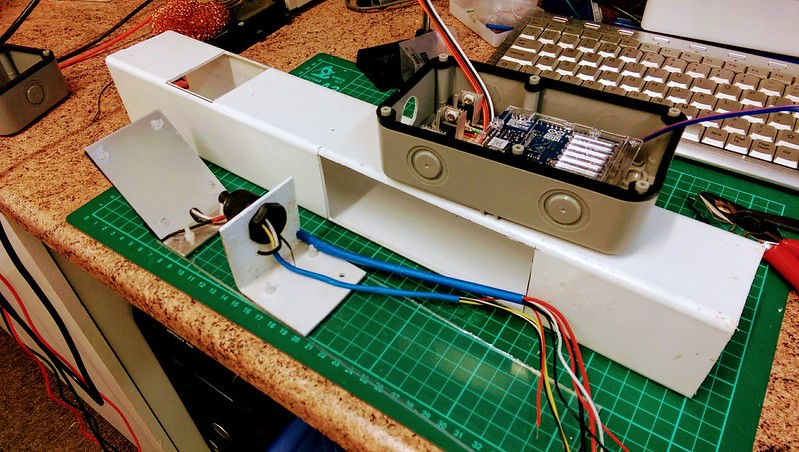
The housing, detector assembly and electronics box
Mirror Heater
The aluminium mirror is the one part of the detector that is exposed to the sky and all that comes from it, be it precipitation, dew and so on. Any form of moisture on the mirror surface will negatively affect the reflectivity. There is not much that can be done about protecting the mirror from the rain, and generally rain means there are clouds. When conditions are clear, meaning no or little cloud, the risk of dew forming on exposed parts is increased. Heating the aluminium gently fixes this problem. Basically, the purpose of the mirror heater is to make sure that the surface of the mirror is maintained a few degrees above dewpoint temperature to ensure that dew does not form on the reflecting surface.
The heater element is to be built from some nichrome wire, commonly found as a heating element in toasters, hairdryers and so on. It is commonly sold in many thicknesses (SWG) and I only need to make sure I calculate the right gauge for the size of heater required.
Calculations
Below is a brief rundown of the calculations required to find what sort of wire was required to build the heater.
Power output
I would like the heater wire to output approximately 0.3 W per cm; being that the wire needs to be approximately 37.5 cm long to cover the mirror back, the total power output \(P_{out}\) will be the following:
Supply Current
Calculating the supply current is quite straightforward. The supply voltage \(V_{supp}\) will be 9 V, therefore:
Total Heater Wire Resistance
Now we need to know what the resistance of the entire length of the heater wire will be in order to get the correct gauge nichrome resistance wire:
So the wire ideally needs to have an overall resistance of 6 ohms once built. This includes an extra few centimetres at the end on which to solder on a supply and ground wire.
Let's say that the total length \(\ell_{total}\) of the wire will be 45.5 cm ; at that length:
Conclusion
Ideally the nichrome resistance wire will need to be rated at \(\text{13.2 }\Omega \cdot m\). The nearest I could find was 30 SWG (0.315 mm) at \(\text{14.27 }\Omega \cdot m\), which is what I bought in the end.
Construction
Having scoured eBay for some wire, the first thing I was did a basic test of what I had bought. Placed one test lead of the multimeter at one end of the nichrome resistance wire and ran the other lead along the wire until I got a reading of 6 ohms. That gave a length of about 42 cm. I then dug out some thin heatshrink tubing and cut a length about 8 cm shorter than the wire. Putting the wire through the heatshrink left 4 cm exposed at either end; these ends for attaching to the supply wires.
Probably the most difficult task in putting this heater together was soldering some stranded wire onto each end of the nichrome resistance wire; the metals don't take to each other all that easily. The easiest way turned out to be knotting the wire and supply wire together and then dropping solder onto that.
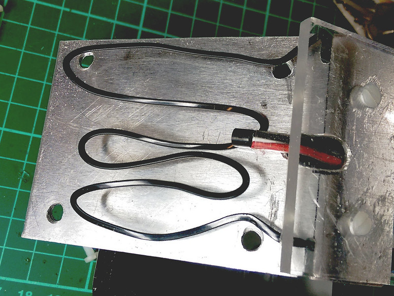
Rear of mirror exposed with heater element and DS18B20 temperature sensor
Once the supply wires were attached I covered the joints with a little more heatshrink to finish the job off. The picture above shows the heater almost in place with the temperature control sensor alongside.
Operation
There is not much to write about this; the solution is not a novel one!
Thermostatic Control
The basic cycle of thermostatic control for the mirror is set out below:
- Define the hysteresis variable \(t_{hyst}\).
- Derive current dew point temperature from a Humidity Sensor \(t_{dew}\).
- Measure the current temperature of the mirror surface \(t_{mirror}\).
- Check the state of condition \(t_{dew} \gt t_{mirror} - t_{hyst}\).
If condition 4 is true then apply heat until condition 4 is false. Once condition 4 is true, switch the heat off. \(t_{hyst}\) is there to ensure that there is a buffer between the dew point \(t_{dew}\) and the temperature of the mirror \(t_{mirror}\) in order to prevent rapid switching of the heater circuit transistor.
Electronics
Control of the heater as above is achieved by using the Arduino to run the thermostatic control cycle, having the DS18B20 to measure \(t_{mirror}\) and an externally situated HTU21D to measure \(t_{dew}\). Using these inputs the Arduino controls the base voltage of a TIP120 Darlington NPN transistor. This transistor in turn controls the voltage to the heater wire.
Below is a mockup of how to wire up an Arduino to control the base voltage of a transistor thus controlling the higher power supply to the (in this case) coil. Of course, the coil symbol in the diagram represents the heater.
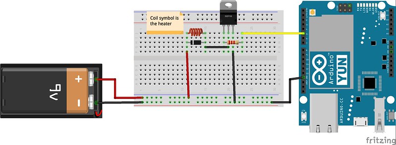
Arduino with TIP120 High Power Control
Humidity Sensor
Sensor Update
I've had some long time concerns about the humidity sensor I had lined up to undertake the task of determining dew point.
Up until recently I had always considered using a DHT22 (also known as an Aosong AM2302) to do the job, but had always been a little unsure of how well adapted this sensor would be to living outside all the time. My uncertainty about their robustness comes mostly from their build quality which, to be polite about it, is not really the best.

DHT22 Humidity Sensor
I suppose that my main concern is how a DHT22 would fare in a cold and wet environment and potentially have its performance degrade leading to short to medium term reliability issues; longer term, I cannot imagine it lasting at all! I could find no satisfactory manufacturer's documentary evidence as to how waterproof the packaging was. There is a good deal of in depth research here comparing the different humidity sensors (or Hygrometers as he calls them) available on the market, for those that are interested in further reading. The DHT22 has an accuracy of around 5% between 0% and 90% humidity. Above 90% humidity the device performance is a little uncertain; no real world data exists, just what is presented in the datasheet. Additionally, Robert from www.kandrsmith.org indicates a 50% device failure rate over a period of 2 years in his research.
So, research into DHT22 alternatives lead me to the HTU21D module.
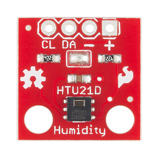
HTU21D Humidity Sensor on a Breakout Board
The stats on the HTU21D look much better; as soon as you take a peek at the datasheet, it becomes obvious that this is a much higher quality product than the DHT series sensor. For a start, there is a proper datasheet rather than the token effort offered by the developers of the DHT22. The build looks much more robust too; both the exterior housing and connector pins are very flimsy on the DHT22, whereas the HTU21D is of a clearly better quality and more robust build.
The HTU21D has a version that comes with a PTFE protector on the sensor window which provides the sensor with a degree of protection from the moisture ingress of an outside environment. Rather than the serial interface of the DHT22, the HTU21D provides I2C communications which I prefer.
Calculating the Dew Point
The dew point temperature measurement is derived from air temperature and humidity both of which are supplied by a humidity sensor. The code I use to derive the dewpoint is written by Rob Tillaart, I cannot even remember when or where I found it, but I have found it useful many times. Below is the code that does the business:
1 2 3 4 5 6 7 8 9 10 11 12 13 14 15 16 17 | double dewPoint(double celsius, double humidity)
{
// (1) Saturation Vapour Pressure = ESGG(T)
double RATIO = 373.15 / (273.15 + celsius);
double RHS = -7.90298 * (RATIO - 1);
RHS += 5.02808 * log10(RATIO);
RHS += -1.3816e-7 * (pow(10, (11.344 * (1 - 1 / RATIO ))) - 1) ;
RHS += 8.1328e-3 * (pow(10, (-3.49149 * (RATIO - 1))) - 1) ;
RHS += log10(1013.246);
// factor -3 is to adjust units - Vapour Pressure SVP * humidity
double VP = pow(10, RHS - 3) * humidity;
// (2) DEWPOINT = F(Vapour Pressure)
double T = log(VP / 0.61078); // temp var
return (241.88 * T) / (17.558 - T);
}
|
Moving from the Uno to the Yún
Over the last year or two I have been experimenting with the Arduino Yún as a replacement for the, ah, mostly reliable Arduino Uno [1]. In the early days I had some interesting times in getting Arduino Unos (and their counterparts) onto my local network, having to resort to some workarounds to ensure reliability.
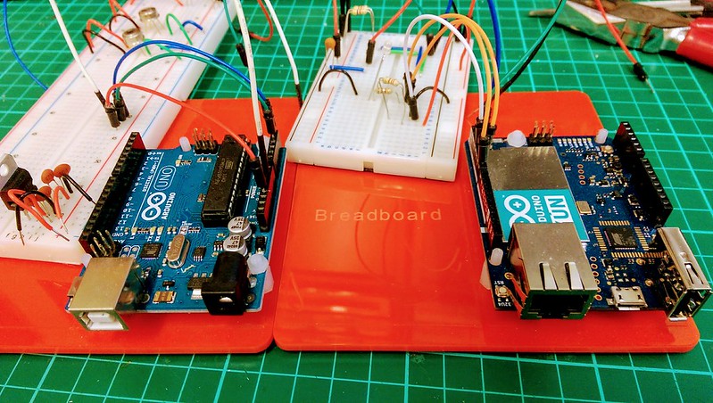
Arduino Uno R3 and Arduino Yún in Comparison
There are a few reasons why I want to move this project over to using a Yún, all of them to do with better reliability and an increased range of functionality. A non-exhaustive list would go something like:
- Much improved networking
- The Yún has built in Ethernet and Wi-Fi support which obviates the need for custom networking hardware and restart handling electronics.
- Better stability
- Over a few months I had the Yún running in a remote situation with real world events taking place, such as swapping out a gateway on the network, power outages (frequent because of where I live!) and so on. I never had any problems getting data from the Yún when I needed to.
- More that just an Arduino
- Of course, the thing that makes the Yún really special is the onboard Linux bridge capabilities that it has. The Atheros AR9331 is basically a Wi-Fi system-on-chip, frequently seen in wireless access points and routers.
The downsides of choosing the Yún are higher initial cost, a more complex architecture and slight incompatibility with some general Arduino libraries.
However, the gain of being able to put an Arduino on the network without breaking any sweat really has me hooked on the Yún. Being that networking comms is taken care of by the addition of the Bridge.h, YunServer.h and YunClient.h libraries, I have an endpoint capable of providing simple and readable RESTful URI resources; something I don't have to even think about programming myself. Because of that, I have the great advantage of more program memory to play with.
Conclusion
So, as can be seen from the collection of things mentioned above, I have moved a long way in getting this project towards completion. It has been a stop / start affair; many other things have intervened and I have had to do some time consuming research. Given the limited free time I have it I do sometimes question whether I will get this finished.
I am hopeful that I will.
Once this build is out of the way and the instrument is outside gathering data the fun really starts.
| [1] | The Arduino Uno has indeed been really trustworthy - a fabulous piece of kit that has given me years of good service. |
Comments
comments powered by Disqus