This is a little project to build a cheap UV exposure box for developing UV sensitive printed circuit boards.
Circuit Construction
I needed an even spread of light from a source close to the board being exposed so I decided to opt for some reasonably wide angle LEDs arranged in a matrix. After some calculations regarding spacing on veroboard, I settled on a figure of about 90 - (3 LEDs in series plus a current limiting resistor between single supply and common rails) times 30.
I headed to eBay to my trusted electronics source and ordered 100 UV LEDs with the following specification:
- Lens Type : Crystal Clear
- Case Style : 5mm Round Flat Top
- Viewing Angle : 120 degrees
- Brightness : 500mcd (Ultra Bright)
- Forward Voltage : 3.2v - 3.8v
- Forward Current : 20mA (typical), 30mA (max)
- Wavelength : 395nm (Ultraviolet A)
Assuming a supply voltage of 12V, each LED operating current being 20mA and a mid-range voltage drop of 3.4V, three LEDs in series should require a current limiting resistor of 91Ω (nearest high value in the 5% resistor range).
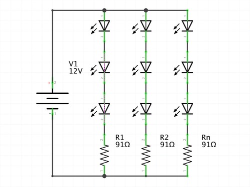
Circuit layout - LED series 1 -> 2 -> n
Construction of the circuit didn't take as long as I thought it would. It was one of those jobs that just rolled along once I got into the rhythm, helped along nicely by using a new (to me, 2nd hand) solder fume extractor. Not sitting in a cloud of burning flux makes the experience so much more pleasant. Anyway, below is a close up of the finished board.
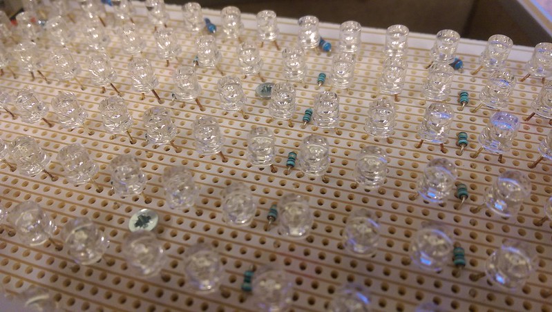
LEDs and resistors in the board
Of course, the worst part is powering up your creation for the first time. Imagine the anticipation, followed by a plume of black smoke. I've been there and it is terrible. So that didn't happen this time; it all lit up beautifully, all 90 LEDs. It was interesting to note that the current draw on my lab bench power supply was around 0.8A - pretty much what I expected. Thankfully no fires, just an intense UV glare from all those LEDs; definitely not good for the eyes.
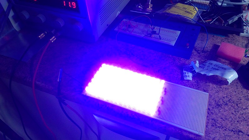
First smoke test - it works!
Box Construction
So the next job was to find a way of boxing the whole thing up and controlling the light by way of opening and closing the lid of the box. At some point one of these cheap fake metal flight cases (by fake metal I actually mean thin wood with some sort of patterned plastic "metal effect" foil) had come into my possession. This seemed to provide the perfect sacrificial offering to my project [1]. Below is a picture of the completed light box, housed in its "quality" housing.
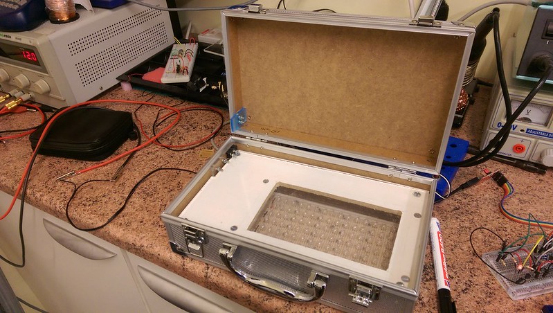
Assembly complete
Below is a close up of the microswitch arrangement. What can I say more than it functions perfectly? Eyes will now be protected when lifting the lid.
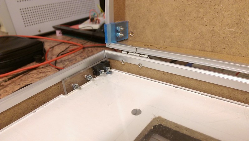
Microswitch in place with actuator
Project Complete
Final in place testing of the on/off switch. Project complete!
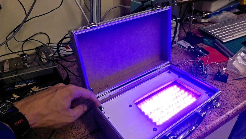
Testing the switch
Above you can see me just giving the microswitch arrangement a quick test. Those UV LEDs are really bright! I am very much looking forward to producing my first circuit board.
| [1] | Bend to the will of my project or be detroyed in the attempt. |
Comments
comments powered by Disqus