Contents
Onwards
This is the next installment on the cloud detection project. This time I am starting to test out hooking up an MLX90614 or two to an Arduino and try out pointing it to the sky in the aim of get some interesting results.
Just as a friendly warning: calculations done here are rough and ready - don't write to me to say that the cat died because of some experiment based on anything shown here. It's all at your own risk, however, just remember the great Mr Churchill's wise words:
The greatest lesson in life is to know that even fools are right sometimes.
With that in mind, onwards with the experiments...
Field of View
My early experiments, as shown in the first installment were interesting because they showed that IR radiation from even a moderately clear sky would measure well below 0°C; clear skies were regularly below -40°C - out of range on the thermometer. However when testing with the first MLX90614 I bought, I found that the readings were much higher averaging only around -9°C for a clear sky.
I believe that this is mainly due to the field of view of which ever thermometer I was using. I therefore set about making some very simplistic calculations.
Digital Hand Held Thermometer
I calculated the field of view (FOV) of this thermometer to be approximately 7.16°. Compare that with the Sun's angular radius of ~0.5°, then you have a rough idea of how much sky is being covered.
Following that, working out the ratio of viewable sky (r) is not too hard. Being that the field of view is 7.16°, the angular radius (θ) is 3.58°, hence:
which gives us 0.000976 - equivalent to about 1/1025th of the whole sky.
Melexis MLX90614 Family
The MLX90614 family of sensors come in many flavours for a massive range of industrial and medical applications- you can find out absolutely everything you'll ever need to know about these sensors in the datasheet right here. For the rest of this post I am going to look at just two variants.
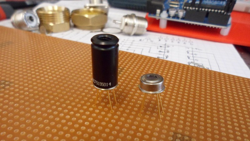
Side by side comparison: BCF on the left, BAA on the right
These sensors sample their ambient temperature as part of the process of measuring infra red object temperature, and as a bonus they make both of these available to the user.
MLX90614 (BAA) Variant
If you were to purchase an MLX90614 from most popular electronics web sites you will more than likely end up with a MLX90614ESF-BAA-000-TU-ND variant in a plain TO-39 package minus fancy lens attachment. Whilst this is probably the cheapest of the MLX90614 family it is also the model with the widest FOV, at a whopping 90° according to the datasheet.
The BAA in the name gives us the option code as described by the datasheet:
- B - 3V supply voltage
- A - Single zone of detection
- A - Standard package (giving the 90° FOV)
The derived θ for this model is 45°, therefore r is 0.146447 giving an equivalent (and rather approximate) view of a massive 1/7th of the sky.
MLX90614 (BCF) Variant
The MLX90614ESF-BCF-000-TU-ND variant of this sensor is a considerably more expensive option; still packaged in a TO-39 case but with a long lens housing. With the price, however, comes a smaller 10° FOV and is built to be more resistant to environmental temperature fluctuations.
Here's what the BCF options give us:
- B - 3V supply voltage
- C - Internal temperature gradient compensation
- F - 10° FOV
The θ for this beast is 5°, with an r value of 0.001903 giving an equivalent view of approximately 1/526th of the sky - very roughly half the value of the digital hand held thermometer.
Hooking up the MLX90614 to an Arduino
Enough of the theory, let's talk about using one.
Connecting to the Arduino
Connecting an MLX90614 to an Arduino is a fairly trivial affair. Looking from the top of the package with the tab at 12 o'clock, there are four legs; clockwise from the tab:
- Ground - connects to any ground on the Arduino.
- Supply - providing you've got the Z3V model, 3.3V on the Arduino is fine.
- SDA - the data line which connects to A4 on the Arduino.
- SCL - the clock line which connects to A5 on the Arduino.
In addition to the above connections a couple of 4k7 pull up resistors are required; one between the SDA line and supply, one between the SCL line and positive. I also like to add a small ceramic capacitor between ground and supply just to stabilise supply voltages a little. You may note that there are two sensors present in the circuit. This presents challenges all of its own, such as how to address more than one sensor in your software. Basically you will need to be able to change the slave address of one of the sensors, as they all come from the manufacturing line with the same address.
I have written up this article here on how to solve that particular problem this article here on how to change the slave address on an MLX90614.
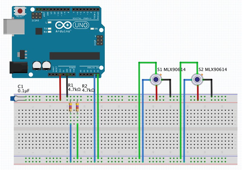
An example of 2 MLX90614 devices and Arduino Uno connected
Software on the Arduino
There aren't a huge number of options for software to get you started on the Arduino; here is just a couple that I found:
- Adafruit have a library here on Github which utilises the Wire library in the background.
- NanoSatisfy host their code on Github which also utilises the Wire library.
I've put together my own library for now which is a slimmed down and lightly modified version of NanoSatisfy's code. Using that, I have written up a quick .ino file which polls both sensors and then outputs a comma separated set of values to the serial port.
Testing the Two Together
After amending the slave address in the BAA variant sensor I assembled the circuit as pictured. I then dug out my 4.8 metre USB lead and placed the Arduino and breadboard in the garden with both sensors side by side, pointing towards an unobstructed view of the night sky. I then uploaded the program and tailed the serial port waiting for data to come in.
Some preliminary test data for both MLX90614 variants
After a couple of hours I turned my log of the serial output into a file, uploaded it to a Google spread sheet and tidied up the presentation a little. Above is a set of 30 sampled results from the test, the samples being taken from the sensors every few minutes.
Conclusion
Below I have graphed a comparison in sky/ground temperature difference between the BAA (blue) and BCF (red) variants, sourced from the test CSV data above. Essentially, the greater the temperature difference between the ground and the sky, the less cloud cover there is.
A graph of both MLX90614 variants compared
It becomes apparent quite quickly that the sensor with the smaller field of view is more responsive to changes in cloud cover, giving a greater dynamic range. This makes sense and was indeed expected, as a sensor's field of view will have a direct relationship with the amount of infra red light it is able to collect from what is, in essence, an infinite distance.
I think that the BAA's ability to see 1/7th of the sky is probably more than what I required for this project. I am only really interested in the sky directly overhead and I think that the BCF will achieve this with the added bonus of better dynamic range.
More testing will be in order, that is for sure, but the indications above seem to me to show that the BCF variant will be the one I will end up using.
Comments
comments powered by Disqus